2.3.4.5. Richon et al. (1985)
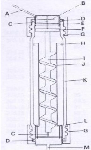
Richon et al. (1985) designed the cell presented in figure 2-6
in order to extend the use of the inert gas stripping technique to foaming and
viscous mixtures. Examples of these are aqueous mixtures of glucides, polyols
and proteins whose viscosities can be as high as 1000 cP. Since a magnetic
stirrer would be inefficient due to high viscosity, the mixture is circulated
inside the internal cylinder from top to bottom, by means of an Archimedes
screw that is maintained by two pivots and activated by a permanent magnet. A
special device is used to break foams without disturbing phase equilibrium
inside the cell. The cell is provided with a bladed screw which prevents liquid
rotation in the cell and promotes the coalescence of gas bubbles.

Figure 2-6: Dilutor cell designed by Richon et
al. (1985) for viscous and foaming mixtures.
A - vapour phase outlet, B -
deflector, C - pivot, D - gasket, E - foam-breaking device, F -
permanent
magnet, G - plug, H - bladed screw, I - Archimedes screw, J - internal
cylinder, K -
dilutor cell, L - carrier gas capillary injectors and M -
carrier gas inlet.
2.3.4.6. Bao et al. (1994)
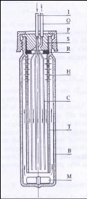
In the design given in figure 2-7 proposed by Bao et al.
(1994), a liquid-conducting tube is placed between the capillaries and the cell
body to create a countercurrent flow of circulating solution to the stripping
bubbles. This is aimed at enhancing mass transfer as well as making the
stripping process more efficient. Bao et al. (1994) used stainless steel
capillary tubes of 0.1 mm inner diameter as dispersion device.

Figure 2-7: Equilibrium cell designed by Bao
et al. (1994).
B - Body, C - capillaries, H - small holes, I - inert gas
inlet, M - magnet, O - vapour phase
outlet, P - plug, R - O-ring, S-seal, T
- liquid-conducting tube.
2.3.4.7. Hovorka and Dohnal (1997)
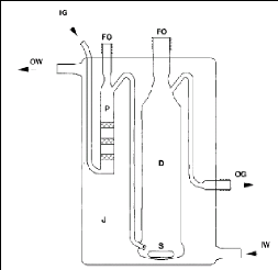
As shown in figure 2-8, Hovorka and Dohnal (1997) designed an
all-glass jacketed device accommodating both the pre-saturator and the dilutor
cell. The pre-saturation compartment is divided by fritted glass disks into
plates in order to allow efficient saturation of the inert gas with the solvent
vapour, yet maintaining a small pressure drop across it. The saturated inert
gas is dispersed in small bubbles into the diluted solution through a fine
porosity fritted glass tip. Liquid droplet entrainment is prevented by the
vapour space of the cell and a special design of the gas outlet. Their set up
allowed measuring infinite dilution activity coefficients in the range from 230
to 70000.

Figure 2-8: Equilibrium cell designed by
Hovorka et al. (1997).
P - Pre-saturator with fritted glass disks, D -
dilutor cell, S - stirrer, J - thermo-statted jacket,
IW - input of
thermo-statted water, OW - output of thermo-statted water, IG - input
of
stripping gas, OG - outlet of saturated stripping gas, FO - filling
openings.
2.3.4.8. Miyano et al (2003)
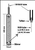
The cell shown in figure 2-9 was used by Miyano et al (2003)
to determine Henry`s law constants and the infinite dilution activity
coefficients of butane, isobutane, 1-butene and isobutene in methanol from (255
to 320) K. A counter flow of liquid against the rising bubbles is achieved in
the inner tube of the cell to increase the contact time. They used a maximum
inert gas flow rate of 2 cm3. min-1.

Figure 2-9: Equilibrium cell designed by
Miyano et al. (2003) for the determination of Henry`s
law constants using
the dilutor technique.
| 


