4.1.2. Experimental set up
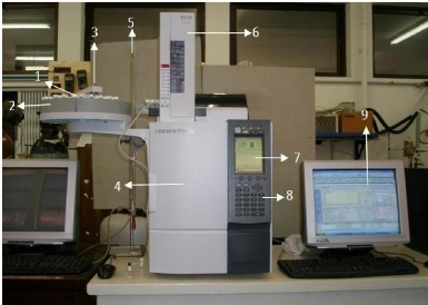
Experiments were performed using a Shimadzu GC-2014 gas
chromatograph apparatus, equipped with a thermal conductivity detector, an
auto-sampler and auto-injector. Retention times and chromatograms related to
each run were made available on a PC monitor by means of a GC solution
workstation software. The set up, shown in Photograph 4-1, is programmable so
that it can carry out injections of samples from 125 different vials and
acquire data with minimum human supervision.

Photograph 4-1: Gas-Liquid Chromatography
equipment.
1. Vials; 2. Tray; 3. Auto-sampler (arm); 4. Column oven; 5. Soap
bubble flow-meter; 6. Auto-
injector; 7. GC screen; 8. Operation panel; 9.
PC monitor
4.1.3. Experimental procedure
The experimental procedure used in this work has been well
documented by numerous authors (David et al. 2003, Letcher et al. 2003a,b and
Deenadayalu et al. 2005). To check for adsorption problems, two different
stainless steel columns of length 1 m and 4.1 mm inner diameter were used with
two different mass percent packings. To avoid adsorption effects, mass percent
packings of the ionic liquid that are large enough were used. Before packing,
the columns were washed with hot soapy water, rinsed with cold water and
flushed with acetone to minimize the drying time. The original and final masses
of the ionic liquid and chromosorb mixture were in agreement to within 0.0005
g. Measurements were done at different temperatures between (303.15 and 373.15)
K, i.e. (303, 313.15, 323.15, 333.15, 353.15, 363.15 and 373.15) K.
Reproducibility was checked by undertaking three experimental runs. It was
observed that retention times were reproducible within 0.05 minutes. The flow
rate of dry helium, the carrier gas, was determined with the aid of a soap
bubble flow meter placed at the outlet of the detector. The flow rates were
corrected for water vapour pressure and varied from 0.3 to 0.7
um3.s-1 .The carrier gas flow rate was allowed to
stabilize for at least 15 min prior to any series of runs. The pressure drop
through the column varied from (25 to 50) kPa, providing conducive retention
times and sharp peaks. The injected volumes ranged between 0.1 and 0.5 ul and
were considered small enough to comply with the condition of infinite dilution
of the solutes on the column. Both the injector and the detector were at
T = 523.15 K. More details on the experimental parameters and
variables needed to compute infinite dilution activity coefficients by means of
equation (3-10), are discussed below.
4.1.3.1 Temperature control
The equipment, not only controls the temperature using a
thermostat, but also displays its value
5
on the monitor. The column oven temperature was known with an
accuracy of #177; 0.01 K and a stability of 0.05 K. The design of the GC was
such that an electronically controlled thermostat was used to reliably control
the column temperature.
4.1.3.2 Pressure measurement
The outlet pressure which is the same as the atmospheric
pressure was measured with the aid of a digital barometer with an uncertainty
of #177;0.30 %. The pressure drop through the packed column was fixed by the
equipment, depending on the inert gas flow-rate set by the operator. The
uncertainty in the inlet pressure measurement was #177;0.50 %.
4.1.3.3 Flow-rate measurement
A bubble soap flow-meter consisting of a 100 ml calibrated
cylinder was used for the determination of helium flow rate. The uncertainty in
the flow rate measurement was estimated as #177;0.20 %.
4.1.3.4 Infinite dilution range
Injections between 0.1 and 0.5ul were considered small enough
to comply with the infinite dilution requirement. It is however advisable to
check whether the retention time for a solute at the selected injection volume
and flow rate remains the same as when it is part of a mixture.
4.1.3.5 Column packing
This is the most critical step when undertaking measurements
via the Gas-Liquid Chromatography technique. Large error margins are caused by
a careless column packing. The uncertainty in determining the mass of the
solvent loaded into the column was #177;0.03 %.
Column cleaning
The column was washed with soapy water and flashed with acetone
to facilitate drying with air.
Determination of solvent number of moles
The following procedure was employed:
1. The mass of an empty flask was measured using a digital
balance;
2. Chromosorb, the solid support for the solvent was added to the
flask and weighed;
3. The amount of solvent to be added was roughly calculated on
the basis of the desired percent loading of the solvent;
4. The solvent was added and its weight found accurately.
Coating the support with the IL
Dichloromethane was added to the flask content to distribute
the solvent evenly on chromosorb. Thereafter, a rotary evaporator was used to
remove the Dichloromethane. This step ended when the mass of the mixture in the
content was equal to the one measured before adding dichloromethane.
Filling the column
The support loaded with IL was filled in the column with the
aid of a vacuum pump. One had to
make sure that the load was equally
distributed inside the column. The mass of the packed
column had to be known before and after each series of runs to
check for a probable elution of the solvent.
| 


