4.6
Ways of recording information
The information will be recorded in My sql database. A
database contains different parts which are used to record and manipulate
information. The following steps elaborate on the components and design of an
ERDM.
4.6.1
Entity Relationship Diagram
An ERD is a specialized graphic that illustrates the
interrelationships between entities in a database. ERD often use symbols to
represent three different types of information. Boxes are commonly used to
represent entities. Diamonds are normally used to be solved while retaining its
essential features one-to-one relationships.
This type of relationship takes place when a single occurrence
of an entity is relationship to just one occurrence of a second entity.
The term entity is widely used in database circles and is used
to mean any distinguishable object that is to be represented in the database.
ERDM is based on a perception of a real world that consists of a collection of
basic object called entities and also of relationships among these objects.
4.6.2
Designing the ERD
Entities are described in a database by set of attribute, like
the attribute username, password, telephone number, employee id and address
describe the entity, employees in the ERDM illustrated below. The primary key
employee id is used to uniquely identify an employees (since it may be possible
to have two employees with same name, surname, etc) the entity relationships
are shown in diamond shapes. The set of all entities of the same type and set
of all relationships of same type are termed as an entity set and relationship
set respectively, the overall logical structure (schema) of a database can be
expressed graphically by an ERD, which is built up from the following
components:
Rectangle: represent entity sets
Ellipse: represent attributes
Diamonds: represent relationship among entity sets
Lines: links attributes to entity sets and sets and entity
sets to relationships
Process
Each component is labeled with the entity or relationship that
it represents.
4.6.3 Entity Relationship
Diagram
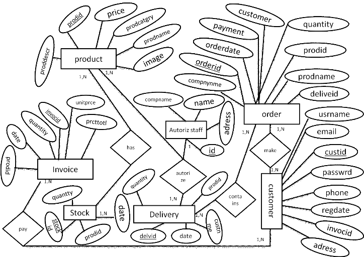
Figure 6: Entity
Relationship Diagram
|